Alma Homepage
Alma System (resumo em português)
·
Create a system able to extract the meaning of a program and to present
it in a clear way using visual explanations of the program behaviour
simulations.
·
Remove language and program dependencies
Alma System:
Design Goals
·
Build an integrated and easy to use environment
·
Avoid the need for any kind of change in the source code
·
Allow the selection of different views of the same program
·
Create a system as generic as possible in order to be used by different
source languages
Alma System:
Architecture
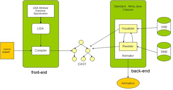
Input and
Output of ALMA
·
INPUT – the specification of FE allows the user to map the conceptual
elements of his language to the DAST nodes
·
OUTPUT – the BE works on that DAST using two bases of rules (visualizing
rules and rewriting rules) and constructs the output – the animation.
Alma System: Internal Representation (DAST- Decorated
Abstract Syntax Tree)
·
Structure of DAST nodes – name of the symbol, production identifier, set
of attributes, children nodes, ... (that will represent names, types and values
of the source program identifiers)
·
The set of symbols is pre-defined and the symbols that can be generated
belong to the abstract grammar of the
·
One node can represent different things depending on the source language
but it must represent the same underlying semantics
·
These nodes are used on the BE rules definition (VRB and RRB)
Alma System: Front-end
n One FE for each language
(grammar) that constructs the DAST using pre-defined methods in the semantic
evaluation (the use of these methods depends on a mapping that associates
concepts of the source program to DAST nodes)
Alma System:
Back-end
n
Independent of the
source language
n It’s the same for all the
FE’s
n
Implements the
algorithm animation
n Works over the DAST based
on a set of visualizing rules (VRB) and a set of rewriting rules (RRB)
n The animation is based on
the internal representation of the source program
n That internal representation
has standard syntax formally specified by a grammar
n The visualizing and
rewriting mapping are easily specified
Animation Algorithm
Is divided into:
Tree walker visualizer
–
Traverses the tree applying the visualizing rules to the appropriate
subtrees
–
Applies several (as many as possible) rules in one traversal
–
Produces the visualization of one state of the program
Tree
walker rewriter
–
Traverses the tree but it applies only one rewriting rule (semantic or
syntactic modification)
–
Then the tree will be ready to be visualized again
Visualizing rules
VRB: DAST ® set (condition ´ drawprod)
Vis_rule(ProdId)
= <tree_pattern>,
(condition),
{drawing procedure}
<tree_pattern>=<root,child1,...,childn>
![]() Note that it can be specified more then one rule for each production
Note that it can be specified more then one rule for each production
Rewriting rules
RRB: DAST ® set(condition ´ newtree ´
attribsEval)
Rew_rule(ProdId)
= <tree_pattern>,
(condition),
<newtree>,
{attribsEval}
![]() Note that it can be specified more then one rule for each production
Note that it can be specified more then one rule for each production
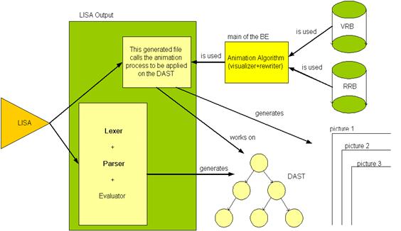
Reusing Lisa System in Alma Implementation
- Lisa System is used to
construct the FE for each new input language of Alma System.
- Some of its Java classes and
editors are used to edit and show the inputs and results of Alma.
Reusing LISA in BE of
The first example is a simple imperative language…
Source text…
a ? ;
b ? ;
let c =
a + b ;
c ! ;
FE construction
rule AlmaAxioma{
PROG ::= STATS compute {PROG.dast = mkroot(STATS.tree);};
}
rule STS {
STATS ::= STAT \; STATS compute {STATS[0].tree = mkstats(STAT.tree,STATS[1].tree);}
| STAT \; compute {STATS.tree=STAT.tree;};
}
rule STATEMENT {
STAT ::=
let VAR =
EXP compute {STAT.tree = mkassign(VAR.tree,
EXP.tree);}
| VAR \?
compute {STAT.tree = mkread(VAR.tree);}
| VAR !
compute {STAT.tree = mkwrite(VAR.tree);};
}
rule EXPR {
EXP ::=
T #opad EXP compute {EXP[0].tree
= mkoper(T.tree,EXP[1].tree,#opad.value());}
| T
compute {EXP.tree = T.tree;};
}
Generated DAST
Generated Animation
|
|
|
|

With a new FE for a robot language and some new
rewriting and visualizing rule we will get very different results….
We will get a
different abstraction level…
Source language grammar
robot → ini_pos moves
ini_pos → “xi =“ INT “yi
=“ INT
moves → moves mov
| mov
mov → dir nsteps
dir →
DOWN | RIGHT | UP | LEFT
nsteps →
INT
Source text
xi= 0
yi= 0
DOWN 3
RIGHT 7
UP 2
LEFT 4
Generated DAST
Rewriting Rules
rew_rule(lstmov)
= <a:lst, b:const, c:const>,
(getvalue(b)!=NULL),
<a:lst, b: const, c:
const>,
{
x=getTableVal(xi);
y=getTableVal(yi);
calculate(x,y,getValue(b),getValue(c))
putTableVal(xi,x);
putTableVal(yi,y);}
rew_rule(passign)
= <at:assign, a1: var, b: exp>,
(getValue(b)!=NULL),
<passign: at: assign,
a2: var, b: exp>,
{ setName(a2,getName(a1));
setValue(a2,getValue(b));}
Visualising Rules
vis_rule(robot)
= <a: procdef, b: stats>,
(),
<a:procdef, b:stats>,
{drawrobot(getValue(xi),
getValue(yi))}
drawrobot(int x, int y){
String
fich = getImage(x,y);
drawImage(“fich.gif”);
}
With a new FE for Prolog programs and using the same rules
used in the first examples we will get the animation below….
Source program
mãe(alda,joana).
mãe(joana,joão).
pai(luis,pedro).
pai(luis joana).
pais(M,P,E) :- mae(M,E), pai(P,E).
Generated DAST
Image nº1

Image nº2
Image nº3
Image nº4
Image nº5